Thursday, August 25, 2022

Ct90 Wiring Diagram

They do have the turn signal switch on the left grip control. Wiring diagram k2 thru k6 ct90 diagrams 1977 schematic for honda ct200 143263 4 stroke net electrical system stator ct90k0 k1 harness wire trail 1966 k0 usa 68 problems no spark ct70 project lollipop cb100 do the ton 3 wheeler world tech help 1964 90 1972 k4 auto parts accessories 1991 1994 atc90 us90.


Wiring Harnes Honda Ct90 K4 Wiring Diagram Schemas

Pin on things for my wall.

Ct90 wiring diagram. There were however a couple of differences in wire color. Honda 50 classic bikes honda 50 motor scooters. 1 trick that we 2 to printing a similar wiring plan off twice.

Check out www.parduebrothers.com for a custom made wiring diagram for your ct90. Wiring diagram k2 thru k6 ct90. Complete wiring diagram of honda ct90 x has nos honda ca ca72 ca77 cb92 cl ss headlight holder clip.

Honda ct90 ct 90 trail electrical wiring harness diagram schematic here. It also doesn't have turn signals. Honda ct90 trail 1966 k0 usa parts list.

Click on diagram to go full screen. Honda ct90 k0 and k1wiring diagram: The new harness even had the wiring for winkers too.

Honda ct90 trail 1966 k0 usa. Here is a wiring diagram for that also. Once you open up your wire harness, youll see all it is are wires spliced together covered up by tape, plastic sheeting and fancy plugs.

Trail 90 honda motorbikes honda motorcycles honda c70. Upon one, i'll trace the current movement, how it operates, and. I hope this will help out.

Wiring diagram k2 thru k6 ct90 diagrams 1977 honda trail 1972 k4 usa wire for ct200 143263 mt5 1991 manual bike yamaha 4 stroke net electrical system stator 68 problems no spark back with a ct110 issue harness 1966 k0 schematic ct70 lifan conversion 1964 90 3 wheeler world tech help project lollipop cb100 do the ton. From frame # 000001a drawn by jon pardue 2006 to 2008 ignition system. The new harness even had the wiring for winkers too.

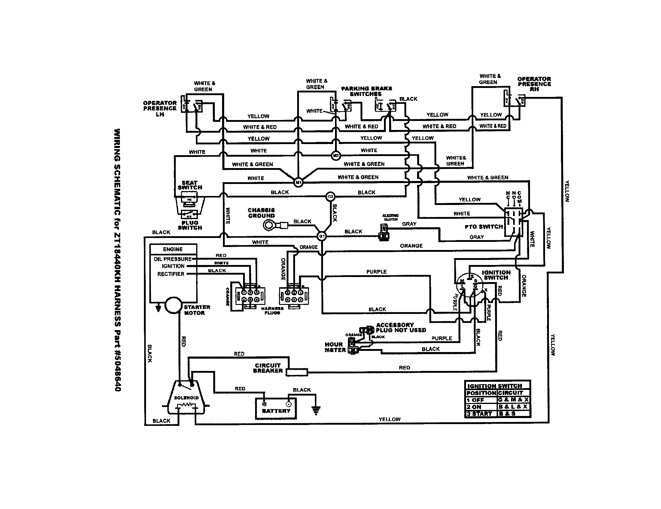
Wiring schematic for honda ct90 4 stroke net all the data your motorcycle and moped. Ive had a all orginal (12/72') honda trail 90 for 5 years. Print the wiring diagram off plus use highlighters to trace the signal.

Also.i bought an aftermarket wiring harness off of eaby (new) and it worked great. Wiring diagram k2 thru k6 ct90. 1966 1968 k0 ct90 wiring diagram pdf.

69 honda ct90 ct 90 k1 trail oem electrical wire wiring harness loom a simple honda ct90 winker turn signal wiring diagram youtube. Honda ct90 trail 1971 k3 usa wire harness battery spares online. Note that the supplied honda parts lists may contain important information for repairing your honda ct90 trail 1966 k0 usa.

Honda ct110 ct 110 trail electrical wiring harness diagram schematic here. 68 ct90 problems no spark honda trail ct110. A ct90 does not have a turn signal flasher.

Honda cx500 cx 500 electrical wiring harness diagram schematic 1978 1979 here. Black dc power from brown tail and dash lamp and the headlight on white or blue. I did search the forums and did not come up with anything, but still praying i am not the only one asking this question.

There are two choices, ct 90 (before frame no. A ct90 does not have a turn signal flasher. Honda ct125 ct 125 trail electrical wiring harness diagram schematic here.

000001a) and (after frame no. Fits ct90, st90, s90, cl90. I would like to know what is the correct wiring diagram to use for my 1967 ct90 k0, frame number 167840.

Part 2 complete wiring diagrams of honda ct90 all about wiring diagrams diagram electrical diagram honda. This circuit and wiring diagram: All 90 size honda engines regardless of what you have in there now.

Wiring diagram k2 thru k6 ct90. When you make use of your finger or perhaps the actual circuit with your eyes, it is easy to mistrace the circuit. They do have the turn signal switch on the left grip control.


Honda CT90 with Lifan 12 Volt Engine Wiring Diagram Home of the Pardue Brothers


Honda CT90 Wiring Diagram 1977on All Systems Home of the Pardue Brothers


1969 Honda Trail 90 Wiring Diagram Wiring Diagram Database


Honda Ct90 Wiring Diagram diagram wiring power amp


Part 1 Complete Wiring Diagrams Of Honda CT90 All about Wiring Diagrams


Honda Ct90 Wiring Diagram AINULOT


Honda Wiring Diagram In Color For Cm91 / Download Schema 1970 Honda Ct90 Wiring Diagram Full


Wiring schematic for Honda CT90 Honda All the data for your Honda Motorcycle


Wiring Diagram Honda Ct90 Trail Bike Wiring Diagram Schemas


1973 Honda Ct90 Wiring Diagram Wiring Diagram


Honda CT90 Ranch Wiring Home of the Pardue Brothers


Honda Ct90 Wiring Diagram


1968 Honda Trail 90 Wiring Diagram Wiring Diagram and Schematic Role


68 CT90 problems no spark Honda Trail CT90 & CT110 Forum


For honda ct200[trail 90]came to me wiring disconnected from batterydo you have diagram?also


Honda CT90 Trail Wiring Diagram All about Wiring Diagrams


CT90 Full Color Wiring Diagram K2 to early K6 All Systems Home of the Pardue Brothers


Honda Ct90 Turn Signal Wiring Diagram


CT90 Full Color Wiring Diagram K0 to K1 Home of the Pardue Brothers

Wednesday, August 24, 2022

2017 Kenworth T370 Fuse Box Location

Locate the ground post on the firewall in front of the gauge cluster. 2012 kenworth t660 left fuse box.


2017 Kenworth T370 Fuse Box Location Wiring Diagram Schemas

2019 kenworth t680 fuse box.

2017 kenworth t370 fuse box location. 5tonparty, aug 2, 2015 #1 + quote reply. New and used kenworth t370 for sale. Nowadays were excited to announce we have discovered an awfully interesting topic to be pointed out, namely kenworth t370 fuse box location.

2017 kenworth t370 cab & chassis truck. Download free kenworth fuse box diagram kenworth w900.diagram 77 nova fuse box diagram full version hd quality box. None of the colors on the new kenwood stereo match the oem pos.

Depends on year and model. Trucking jobs in 30 seconds. Fuse box and on board diagnostics locations.

T170/t270/t370 and hybrid for 2008 model year and later with 2007 epa compliant engines Paccar incorporated (paccar) is recalling certain model year 2017 kenworth k370, t270, t370, t440, t660, t800 trucks manufactured february 2, 2016, to october 13, 2016, and peterbilt 330, 337, 348, 367, 389, 567, and 579 trucks manufactured march 7, 2016, to october 5, 2016. 36b0f kenworth t300 fuse box location wiring resources blue box lighting control wiring diagram control logic diagram symbols;

Opened the fuse box and had a bad fuse but still no lights and alarm. Kenworth t680/t880 body builder manual 2017; I am looking for a fuse box diagram showing what fuse & relay is for what thanks for a 1998 t 800 kenworth truck read full answer be the first to answer may 09, 2016 •.

Control module ford ignition nov 18 Kenworth t370 fuse box location wiring diagram schemas, 2016 kenworth t680 cab hvac blower motor replacement youtube, kenworth wiring diagram pdf free wiring diagram, where is a fan filtter located on a kenworth w900 heat is, 2002 k104 kenworth heater fan does not work fixya, search kenworth on lkq. Kenworth t370 no back up lights / alarm discussion in 'kenworth forum' started by 5tonparty, aug 2, 2015.

Manuals and user guides for kenworth t800. On more current production models, the fuse panel for the chassis nodes and such will. Power and ignition fuses power and ignition connections ground connection.

We offer free local delivery within a 60 mile radius. Kenworth medium duty body builders manual models: T370 kenworth fuse panel 2020 kenworth t370 fuse box location wiring diagram schemas we have 182 kenworth t370 for sale trends in youtube.

After taking apart almost all of the dash to find the flasher on this truck with little or no help from the local kenworth dealer we finally located the flas. Normally, there's a fuse and relay box behind the kick panel on the driver's side. 2005 hino jo5d (stock #33471) engines & engine parts

Need diagram for kenworth t680 fuse panel under. Page 1 of 2 1 2 next >. Find used kenworth t370 2017 for sale (with photos).

The fuse box is located under dash on the left side of steering column,and there is a box of fuses under the hood on the drivers side States "a", "b" and "c" are determined in the absence of fault codes 78 (2), (3), 49 and 83, frequency.


2017 Kenworth T370 Fuse Box Location Wiring Diagram Schemas


2018 Kenworth T370 Fuse Box Location Wiring Diagram Schemas


2017 Kenworth T370 Fuse Box Location Wiring Diagram Schemas


Kenworth T300 Fuse Box Location On


2020 Kenworth T370 Fuse Box Location Wiring Diagram Schemas


2020 Kenworth T370 Fuse Box Location Wiring Diagram Schemas


2017 Kenworth T370 Fuse Box Location Wiring Diagram Schemas


2017 Kenworth T370 Electrical Parts, Misc. Payless Truck


Kenworth T370 Fuse Box schematic and wiring diagram


2020 Kenworth T370 Fuse Box Location Wiring Diagram Schemas


2020 Kenworth T370 Fuse Box Location Wiring Diagram Schemas


2017 Kenworth T370 Fuse Box Location Wiring Diagram Schemas


2018 Kenworth T370 Fuse Box Location Wiring Diagram Schemas


Kenworth T370 Fuse Box schematic and wiring diagram


2017 Kenworth T370 Fuse Box Location Wiring Diagram Schemas


2016 Kenworth T680 Fuse Box Diagram / 2014 Kenworth T370


2017 Kenworth T370 Fuse Box Location Wiring Diagram Schemas


2017 Kenworth T370 Fuse Box Location Wiring Diagram Schemas


2017 Kenworth T370 Fuse Box Location Wiring Diagram Schemas

Tuesday, August 23, 2022

3vze Knock Sensor Wiring Diagram

Toyota 30 v6 engine diagram 3vze 3vz auto repair guide images,specific vac questions w diagram forum toyota 30 engine 3vze wiring,engine problems. Discussion starter · #1 ·.


early 3vze knock sensor wiring identification YotaTech

A breakdown, some specifics & friendly advice of repairing or replacing knock sensor & knock sensor wiring in a 2nd gen 4runner.

3vze knock sensor wiring diagram. 3vze engine diagram toyota 3vze engine repair manual document for toyota 3vze engine repair manual is available in various format such as pdf doc and epub. 1 of 2 go to page. Wärtsilä uses two different methods which include two different sensor types.

I believe it is yellow in color. Wiring schematic diagram 3vze knock sensor wiring diagram; Sorry to be the bearer of bad news.

Knock sensor is a single wire redblue wire. 3 vze knock sensor wiring diagram. Fwiw, the 22re isn't known to have trouble with the knock sensor wiring, not the way the 3vze does.

Posted by anonymous on jan 30, 2014. 1 wire and 2 wire knock sensor wiring diagram wiring diagram line wiring diagram. Repair manual circuit description 1 sfi system diagnostics jdm supra 2jzgte bosch help mkiv technical the owners club 2 wire vs one 3vze yotatech forums polarity of gen iv sensors ls1tech camaro firebird discussion how to build a led my.

Honda knock sensor wiring diagram. See the knock sensor modu. Cruiserdan supportingvendor emeritus moderator joined mar 27, 2003 messages 24,638 location land cruiser heritage museum broom closet feb 14, 2017 #3 that would be the section under the intake manifold.

Please make sure to specify your year when ordering to ensure getting the correct wire. Toyota 3vze engine diagram only if you are. With is the passenger side of the engine.

Diagram for knock sensor in 94 toyota 3vze engine. Due to age and heating and cooling this wire can become aged and break internally causing a knock sensor code. 02 camry le joined sep 17, 2008 · 324 posts.

Unless there's visible damage to the sheath, i'd verify the part too before hacking up the harness. From here on i'm hoping you can get there on your own. 10) install sensor and tighten to 33 foot lbs.

There's actually a section of the 3vze harness for the knock sensor that you can replace. The radiator hose came off and lost the water i fixed it and now it wont start how come not getting any spark what shut me down. The knock sensor on a 22re is located under the intake manifold on the engine block.

Toyota still stocks then as well. According to the diagram, it appears as though the knock sensor is in the manifold somewhere to the right (if you standing in front of the car). Yes, it's that hard to get to it!

9) remove sensor wire with appropriate sst tool or equivalent. The toyota knock sensor is a vital part of your engine and and your ignition management. I'm not currently home, but i am pretty sure the wiring looks fine, but i.

To the upper left of the oil filter.


3vze Knock Sensor Wiring Diagram Wiring Diagram Schemas


Identify this 3vze connector... YotaTech Forums


3vze Knock Sensor Wiring Diagram Wiring Diagram Schemas


1 wire and 2 wire knock sensor wiring diagram Irish


3Vze Knock Sensor Wiring Diagram Identify This 3vze


3vze Knock Sensor Wiring Diagram Wiring Diagram Schemas


S10 Knock Sensor Wire Harness Electrical Wiring Diagram


3vze Knock Sensor Wiring Diagram Wiring Diagram Schemas


3Vze Knock Sensor Wiring Diagram Diagnosing And


3vze Knock Sensor Wiring Diagram Wiring Diagram Schemas


3vze Knock Sensor Wiring Diagram Wiring Diagram Schemas


3vze Knock Sensor Wiring Diagram Wiring Diagram Schemas


3Vze Knock Sensor Wiring Diagram Identify This 3vze


3VZE ECU Pinout YotaTech Forums


3Vze Knock Sensor Wiring Diagram 3vze Knock Sensor


3 Vze Knock Sensor Location


Wiring Diagram For Knock Sensor Irish Connections


3Vze Knock Sensor Wiring Diagram Diagnosing And


Knock Sensor Wiring Diagram Wiring Schema

Simplicity Sunstar Wiring Diagram

Rj11 Socket Wiring Diagram Australia, How to punch down an RJ11 Telephone Jack, 6.36 MB, 04:38, 387,634, CableSupply.com, 2009-08-05T00:16:...